Sections of the site
Editor's Choice:
- Creating subtitles in Subtitle Workshop
- Laser therapy (laser therapy) Laser therapeutic device "Matrix" What does the laser therapy device Matrix treat?
- Fraudulent subscriptions and fraud in Telegram Subscribers for telegram channel
- Specialty "Infocommunication technologies and communication systems" (bachelor's degree) Infocommunication technologies and communication systems 11
- Odnoklassniki: how to open my page
- How to submit water meter readings in Kazan State services portal RT meter readings
- Outputting part of an image html sprite
- Setting up additional details and additional information for 1c nomenclature additional details and information differences
- What to do when there is no registration data
- Request for data selection (formulas) in MS EXCEL Excel selection by condition macro
Advertising
| Connecting the telephone socket rj 45. Connecting the Internet sockets Legrand, Cable (diagram) |
|
Despite the rapid development of wireless communications, RJ-45 outlets are still essential elements of the structured cabling system of a modern building. We suggest considering their structure, types, pinout options and installation methods. The apparent simplicity of the question can be misleading, since there are certain nuances that need to be paid attention to. Design featuresDespite the variety of types of sockets for twisted pair, their design is almost identical, with the exception of small details. As an example, let's look at a typical external single-port device. Rice. 1. Basic elements of an external RJ-45 socketDesignations:
Externally, the socket resembles an RJ-11 telephone standard; the main difference is the number of connector pins, there are eight of them, not four. Accordingly, a computer socket can be used as a telephone socket, but not vice versa. U various types devices may have minor characteristic features, but in general the design concept remains unchanged. Types and characteristicsThe main parameters of these switching devices are determined by the following criteria:
Let's briefly talk about each of them. More doesn't mean better. One of the main parameters is the number of ports. As a rule, there can be from one to four. If you need to use a larger number of connections, it is easier to install a patch panel, but such a need indicates an ill-conceived network layout. In addition, it should be taken into account that a large number of patch cords connected nearby causes some inconvenience.  Rice. 2. Krauler 4-port external socket Rice. 2. Krauler 4-port external socket In practice, when organizing an office or home LAN, one and two-unit modules are mainly used. This parameter is directly related to the characteristics of the cable used for installation computer network. We are talking about bandwidth, which determines both the data transfer speed and the possibility of using special network technologies. Below is a table that shows the relationship between category and bandwidth.  Currently, when installing a LAN, cables with a category lower than 5e are practically not used. Execution. The method of mounting the switching device depends on this parameter. There are two versions:
 Internal two-port RJ-45 socket disassembled and assembled Internal two-port RJ-45 socket disassembled and assembled As a rule, the choice of one version or another depends on how the LAN wiring is done. If it is external (for example, laid in boxes), external sockets are used. In cases where hidden wiring is done, the internal devices look more aesthetically pleasing. Separately, it is necessary to highlight the sockets that are installed directly on the box. Technically, such execution can be considered both internal and external.  On specifications LAN execution has no effect. Modular designs. Speaking about performance, we cannot fail to mention modular designs. This solution allows you to assemble a socket for certain combination, for example, install in RJ-45 and RJ-11 modules or with different categories.  RJ-45 pinoutThere should be no problems with this, since opposite each contact group there is a color marking that complies with the T568A and T568B standards (can be marked with the letters “A” and “B”, as in the figure below).  It doesn’t matter which standard is used, the main thing is that it is the same type for the LAN, otherwise problems are guaranteed. It is believed that we have adopted a “crimp” type T568B, but this is a rather conditional statement. If you do not know which standard your provider uses, then you can install it using the pinout of the connector installed on the cable entering the apartment.  Detailed connection instructionsLet's start with the tool that you will need to seal twisted pair sockets. Ideally, it is advisable to purchase a universal extractor (shown in Figure 9). It allows you to press and cut the rest of the wire in one movement. Thanks to Chinese manufacturers, such a universal tool costs about 3-4 dollars. The price of branded products can be 2-3 times more expensive.  Rice. 9. Universal extractor Rice. 9. Universal extractor This tool has a special mechanism that allows you to press the wire between two contact knives and cut off its excess (3 in Fig. 9). In addition, it is equipped with a flat screwdriver (2) and a hook (1), which allows you to remove the wire if it is incorrectly terminated. The cost of a universal extractor is relatively low, but the benefits are quite tangible. No less useful are universal insulation stripping pliers. They cost about the same as an extractor and can cut Ø3.5-9 mm cables such as UTP, STP, FTP. It is possible to adjust the depth of the cut.  It is not advisable to use a knife to strip the insulation, since in this case there is a high probability of damaging one of the twisted pair wires. Having dealt with the necessary tools, let's move on to the algorithm for embedding a twisted pair cable into a switching device. We will assume that the cable has already been laid and the outlet space has been prepared. The procedure is as follows:
 Rice. 11. A – cable with wires routed to clamps, B – pressed in with an extractor Rice. 11. A – cable with wires routed to clamps, B – pressed in with an extractor On at this stage Let's make a small digression regarding the use of improvised means for pressing. Sometimes you can find advice in which, in the absence of the necessary tool For pressing, it is recommended to use a utility knife or a thin slotted screwdriver. This approach can only be used as a last resort, when access to the network is urgently needed, but there is no tool at hand. But in the future, such a socket must be clamped. Otherwise, there is a high probability of losing contact between the wire and the latch after some time. We also note that many branded manufacturers include a simple plastic extractor for each socket, which allows you to securely seal the wire, after which all that remains is to carefully trim off the excess.
When using a shielded cable, you must install an appropriate socket that has a shield connection. Otherwise, it turns into a large antenna, which will immediately affect the bandwidth, and, consequently, the data transfer speed. For the same reason, you should not use an STP or FTP cable if ungrounded equipment is connected to it. Twisted pair LAN technology requires the use of continuous lines. Twists and adhesions are unacceptable; this leads to serious losses. If it becomes necessary to extend a piece of cable, special connectors should be used for this purpose.  Rice. 12. Twisted pair connectors Rice. 12. Twisted pair connectors These devices are a box in which a board is installed with two RJ-45 connectors (A in Fig. 12), or twisted pair clamps, like sockets (B in Fig. 12).
There are two main types of sockets - for hidden and external cable routing. In this case, we consider independent crimping of a hidden RJ45 network socket. But there are no fundamental differences from the second one in the execution of work, with the exception of the presence of additional work on installing the socket box! Therefore, focusing on this example, you can easily crimp a power socket of a hidden or external type yourself. So let's start with this: twisted pair brought out into the socket. If the ends of the cable are too long, they can be cut off.
It’s easy to determine the desired pinout! To do this, you should look at the crimped end of the patch cord you have (for example, cut off from the cable) and look at how the wires are located there. If, as in the photo below, then crimping the power socket should be done according to diagram “A”
In a modern house or apartment, it is impossible to get by with just one electrical outlet. This fitting element is designed to transmit a computer signal from one system unit to another. One of the most frequently installed devices is a combined computer-TV socket. The ease of use of this element is achieved by installing an rj11 telephone connector in one housing. Such a device allows you not only to connect your computer to home network, but also to make the connection landline phone with the network.
Before you find out how to connect such a device, you need to understand what models of computer fittings exist. Types of rj45 socketThe rj45 computer socket can be of a surface-mounted type or for installation using internal mounting. If you plan to install an internal model, then.
Combined sockets with external RJ11 are also in demand for connecting computers in the office.
If you need to connect more than one computer to the network at one workplace, then the dual model will completely eliminate the various devices that are used to increase the number of ports. Computer socket wiringCorrect installation, regardless of the model of the element being installed, will allow you to safely use expensive computer equipment. If the computer socket is not connected correctly, sensitive microprocessor equipment may be damaged. The signal is transmitted from one outlet to another using a twisted pair cable. If the T568B standard is used (used more often), then the wiring is as follows:
Connecting the socket to the cableWhen connecting, the computer socket must be connected to the cable in such a way that inadvertent loss of the conductor from the clamping contact is completely prevented. To do this, you must correctly connect the device to the high-speed cable. The connection is made using a special plug. The plug should be of the required size; the thickness of the tool tip should not exceed the diameter of the wire.
Some installers, in order to save money, use a slotted screwdriver of the appropriate size instead of a special plug. But this method is artisanal, sometimes leading to wire breakage or weakening of the clamp contacts. Although there is also a place to live. When connecting the cable, there is no need to strip the wires. The knives that are built into the connector clamp reliably cut through the insulating shell. Wall socket installationComputer and externally. How to install this element depends on personal preferences and the advisability of using a particular model of such a device.
Most often, the installation and connection of an Internet outlet related to low-current lines is carried out in a triple block:
 For most models, for example from Schneider Electric (Unica series), Legrand, Lezard, the installation principle is almost the same and does not contain fundamental differences. Let's take a step-by-step look at the entire cycle of connecting an Internet outlet. Internet cable Installation begins with installing the router in a low-current switchboard and connecting it to a 220V power outlet. Next, a 4-pair UTP series 5E cable is laid in a separate cable channel or groove not connected to power lines. This cable provides connection speeds of up to 1 Gigabit per second over a distance of up to 100m. Here are its technical characteristics: There are shielded and unshielded varieties. Foil acts as a shield in networks where there is normal grounding. One such 5E cable (4 pairs) can only connect two sockets. In this case, 2 pairs will be involved separately. Installation is carried out with a single wire directly from the switchboard to the socket box. Lead the cable into the installation box and leave the necessary margin - from 15 cm or more. Installation of an internet outlet First remove the cover from the socket and pull out the caliper for ease of installation. If the design of the socket allows, the frame can be mounted initially on the socket box. Thanks to the grooves in the frame, you can easily adjust its horizontal position. Use 3*25mm screws to pre-tighten the entire structure. At the same time, you check the accuracy of the installation with a Pocket Electric level and tighten the screws completely. Manufacturers have recently begun to make frames from aluminum alloy; they are, of course, stronger in design, but will not be magnetic to the level. You will have to support it with one hand. Next, bite off and leave a supply of wire in the socket, a maximum length of 15 cm. Remove the top layer of insulation from the UTP cable. To remove insulation, so as not to damage the conductors, it is better to use special tool- stripper. But you can do all this carefully and with an ordinary stationery knife. The top layer of the cable must be cleared to a length of no more than 2.5 cm. Cut off the excess thread in this case that goes between the cores. A strong thread in twisted pair cables, often used to facilitate opening the sheath over long lengths. It’s even called that – a breaking thread. In telephone cables, it separates bundles and layers. Lightly unravel the veins individually. Next, pull out the inner part of the socket with the contacts. As a rule, any brand, be it a TV, an Internet outlet or a regular 220 Volt, should come with instructions. Instructions for the Schneider Electric Unica internet socket – Standards and connection diagram
For example on Unica:
 If you figure this out, then there will be no difficulties with further installation. Protocol “B” follows the color scheme according to the EIA/TIA-568B standard. One side of the clip should have the following colors:
On the other side:
Pass the wire through the cap. In this case, as mentioned above, the top layer of UTP cable insulation should not be removed by more than 2.5 cm. You cannot strip it right up to the wall of the socket box, as is done with conventional NYM or VVGnG cables. The section without insulation must be of a minimum length. All these twists are not done easily. Their exact quantity per 1 meter of cable is strictly calculated and regulated. Otherwise, when incorrect connection and stripping, not only the speed, but also the quality of data transfer may decrease. Next, insert all the wires into the contact grooves by color. Then you simply snap the lid on. Extra sections of cores that protrude outwards You need to cut it off after closing the lid. The outlet is actually already connected. All that remains is to insert it into place in the caliper. The main advantage of such Internet sockets is that with them there is no need to remove the insulation from the cores and expose it to copper. Special knives are already installed inside the socket itself. When you close the lid, the blades automatically cut through the insulation and create a contact connection. The instructions for such brands often indicate that when connecting the wire, the use of special crimpers is prohibited. It’s as if it’s already in the design. That is, when the lid is closed, it itself cuts off the insulation and lays the wires to the required depth of the connector. Connecting to the router and crimping the connector
Remove the insulation from the other end of the cable by 2-3 cm. The wires are fluffed up and inserted in a certain order, according to the TIA-568B standard, or simply “B”. The arrangement of colors is considered from left to right:
 Standard "A" is sometimes used if you need to connect one computer to another. Here you crimp one end of the cable according to standard “B”, and the other according to “A”. In general, if both ends of the cable are crimped to the same standard (AA or BB), then this is called a patch cord. And if they are swapped (AB or BA), then it is a cross. Again, there is no need to strip the veins. Just insert them into the connector until it stops. After which all this is pressed in with a special crimper. Some people do this with a thin screwdriver or a knife blade, although this can easily damage the connector. The cat5E and cat6 cables in the RJ45 connector are crimped according to the same principle. Another "fork" is not required here. Cables differ in data transfer speed; cat6 has a higher speed. Checking your Internet connection After installing the Internet socket and connector at the other end of the cable, it is advisable to check the connection and integrity of all connections. This can be done with the cheapest Chinese device. What is its essence? There is a signal generator that sends pulses according to certain codes, and a receiver. The generator is connected to the location where the router is installed, and the receiver is connected directly to the outlet itself. After the pulses are applied, the signals are compared. If everything is in order, the green LED lights on the receiver body light up one by one. If there is a break somewhere or short circuit, then one or more lights will not light up at all. When this happens, the first thing to blame is poor contact in the connectors. Most often, it is there, on any core, that the insulation is not completely cut off and, accordingly, there will be no connection. At the very end, a ready-made, tested cable with a connector is connected to the router. A complete set of all tools for cutting, crimping, and testing UTP Internet cables can be ordered on AliExpress (free delivery). How to connect 4-wire telephone cable
Simple color matching won't help here. That is, if you insert the white-blue core into contact with the white-blue marking and connect all the other wires in the same color, there will be no signal. This is explained by the fact that to transmit the signal you need to use contacts 1-2-3-6. On one side, connect two wires to contacts 1-2: green = blue lived  In this case, everything should work without problems. Just remember that here the most important thing is not the colors, but the positions. Colors are used to make it visually easier to distinguish the positions of the same core at different ends of the cable. Also keep in mind that when using 4 wires, i.e. two pairs of twisted pair, you can achieve speeds of up to 100Mbps. But for a gigabit network (1Gbit/sec) you will already need all 8 wires. Errors when connecting an Internet outlet 1 Incorrect connection of cores according to the protocol.You can easily confuse the order of the wires on the connector and in the socket itself. Roughly speaking, turn them 180 degrees. Here everything is checked by a more careful study of the inscriptions on the body of the socket and the color of the wires themselves. A tester with a signal generator and receiver is a good helper for identifying such errors. If the wires are connected incorrectly, the lights on the tester will light up not in order from 1 to 8, but in random patterns. For example, first 1, then immediately 3, then 2, etc.
And if you left the supply of cable in the installation box small, then you will face a big headache. As mentioned earlier, the result here is a deterioration in the speed and quality of the signal. Moreover, there is no need to first unravel the twisted pairs to the point where the insulation is cut, especially with a screwdriver. Simply embroider them by spreading the strands to the required length to fit them into the slots. According to the standard, it is not allowed to unwind a twisted pair cable by more than 13mm, otherwise in tests frequency characteristics Crosstalk errors will appear. In practice, problems will begin when the network is loaded with traffic.
In many families, several devices connect to the Internet: without world wide web We don’t even imagine life, that’s why everyone needs their own line. They work mainly using a wireless protocol - Wi-Fi, but there is still a wire, since so far wired Internet more stable than wireless. During repairs, all wires are hidden in the walls and “Internet” wires are no exception. They, like electric ones, are plugged into sockets, only of a different standard: they are called computer or information. They can have different connectors, but the most common is RJ 45. You can do the installation and connection yourself, but since the connector looks unusual in appearance, there are more than two or three wires in it, and the connection is not ensured by soldering or twisting, you need to know , how to connect an Internet outlet and also the connector that should be inserted into it. Crimping RJ-45 connectorThe Internet cable entering an apartment or house, most often called twisted pair, often ends in a small plastic connector. This plastic device is a connector, usually RJ45. In professional jargon they are also called “Jack”. Its body is transparent, so wires of different colors are visible. The same devices are used on connecting wires that connect computers to each other or to a modem. Only the order of arrangement (or, as computer scientists say, pinout) of the wires can differ. The same connector is inserted into a computer socket. If you understand how the wires are distributed in the connector, there will be no problems connecting the Internet outlet. Internet cable connection diagram by colorThere are two connection schemes: T568A and T568B. The first option - “A” is practically not used in our country, and everywhere the wires are arranged according to the “B” scheme. It is necessary to remember it, since it is what is required in most cases.
To finally clarify all the issues, let's talk about the number of wires in a twisted pair. This Internet cable comes in 2-pair and 4-pair versions. To transfer data at speeds up to 1 Gb/s, 2-pair cables are used, from 1 to 10 Gb/s - 4-pair. Today, apartments and private houses are mostly supplied with flows of up to 100 Mb/s. But with the current pace of development of Internet technology, it is quite possible that in just a couple of years the speeds will be measured in Megabits. It is for this reason that it is better to immediately expand a network of eight rather than 4 conductors. Then when changing speed you won't have to redo anything. The equipment will simply use more conductors. The difference in cable price is small, and sockets and connectors for the Internet still use eight-pin ones. If the network is already wired in two pairs, use the same connectors, only after the first three conductors laid according to scheme B, skip two contacts and place the green conductor in place of the sixth (see photo).
Crimping a twisted pair cable into a connectorThere are special pliers for crimping wires in the connector. They cost about $6-10 depending on the manufacturer. They are more convenient to work with, although you can get by with a regular screwdriver and wire cutters.
First, the insulation is removed from the twisted pair. It is removed at a distance of 7-8 cm from the end of the cable. Under it there are four pairs of conductors of different colors, twisted in twos. Sometimes there is also a thin shielding wire; we just bend it to the side - we don’t need it. We untwist the pairs, align the wires, spreading them in different directions. Then fold according to pattern “B”.
The procedure for sealing the RJ-45 connector in the connector We clamp the wires in the required order between the thumb and forefinger. We lay out the wires evenly, tightly to each other. Having aligned everything, we take wire cutters and cut off the excess length of the wires laid out in order: 10-12 mm should remain. If you attach the connector as in the photo, the insulation of the twisted pair should begin above the latch.
We insert the twisted pair with the cut wires into the connector. Please note that you need to take it with the latch (protrusion on the lid) down.
Each conductor must get into a special path. Insert the wires all the way - they should reach the edge of the connector. Holding the cable at the edge of the connector, insert it into the pliers. The handles of the pliers are brought together smoothly. If the body has become normal, no special effort is required. If you feel that it “doesn’t work”, double-check whether the RJ45 is installed correctly in the socket. If everything is fine, try again. When pressed, the protrusions present in the pliers will move the conductors to the microknives, which will cut through the protective sheath and ensure contact.
This connection is reliable and problems rarely arise with it. And if something happens, it’s easy to re-terminate the cable: cut it off and repeat the process with another “jack”. Video tutorial: crimping an RJ-45 connector with pliers and a screwdriverThe procedure is simple and easy to repeat. Perhaps it will be easier for you to do everything after the video. It shows how to work with pliers, as well as how to do without them, and do everything with a regular straight screwdriver. How to connect an internet cable to a power outletNow we come directly to how to connect the Internet outlet. Let's start with the varieties. Like regular electrical sockets, information sockets come in two modifications:  According to the number of connection points, there are single and double computer sockets. Although computer sockets differ in appearance, the principle of connecting conductors is the same. Eat special contacts, equipped with microknives. The protective sheath is cut through the inserted conductor. As a result, the metal of the microknife contacts fits tightly to the metal of the conductor. How to connect a computer wall socketInside each outlet there is a hint on how to place the wires when connecting the Internet cable. Manufacturers stick on the color scheme that we saw when crimping the connector. There are also two options - “A” and “B”, and we also use option “B”.
The case is mounted on the wall, usually with the cable inlet up and the computer connector down. The next steps are simple:  Connecting a twisted pair cable to an outlet is really a simple procedure. Even the first time it will take a few minutes. You can see again what they do and how in the video. It first shows the connection of an Internet cable with 4 wires, then with 8.
How to connect an internal Internet socketWe won’t describe the installation of the plastic box - that’s a different topic. Let's look at the features of connection and assembly. The main problem here is how to disassemble computer sockets. When connecting conductors to them, you need to get to the contact part: a small ceramic or plastic case with built-in microknife contacts. The conductors are connected to this mounting plate, and then the housing is reassembled. And the whole problem is that different manufacturers they are assembled/disassembled differently. For example, from the popular manufacturer of computer sockets Legrand (LeGrand), in order to get to the connectors in the Legrand Valena RJ45 computer socket, you need to remove the front cover. Under it you will find a white plastic impeller (as in the photo), with an arrow on it.
You need to turn the impeller in the direction of the arrow, after which you will have the housing and the contact plate in your hands. It has color-coded conductors. The connection is no different, except that first you need to thread a twisted pair into the hole on the plate, and then separate the wires. For clarity, watch the video. Another popular manufacturer of such equipment is Lezard. His system is different. The front panel and metal frame are fixed with small bolts. They are easy to unscrew, but the internal contact plate is held in place by clamps. When assembling and disassembling Lezard computer sockets in the right places, you need to press out the contacts with a screwdriver.
To remove the plastic contact group from the housing, you need to press the latch located on the top. After which you will have a small box in your hands. But that's not all. It is necessary to remove the plastic cover that covers and presses the conductors. Remove it by prying up the side petals with a screwdriver. The plastic is elastic and the effort required is quite decent. Just don't overdo it: it's still plastic. After that, the wiring is standard: according to the markings on the sides (do not forget that we are using diagram “B”).
If you know how to connect an Internet outlet, it’s not difficult to figure out even an unfamiliar model. And now you can upgrade your network yourself (increase the length of the twisted pair, move the computer to another location, make another connection point, etc.), without involving specialists. One more question remains: how to connect double sockets. Two cables are connected to them and then the color scheme is added. This is possible when your network is formed by a modem or two Internet lines are connected. Is it possible to connect both inputs with one cable? It’s possible, but you need to avoid getting confused in the color designation of the wires in the further wiring of the network (remember which color you used instead of which). |
 After this, remove the top layer of insulation. There are special tools for this. If they are not there, then a similar operation can be performed using a regular stationery knife. The main thing is not to damage the twisted pair wires! Otherwise, the cable will have to be cut again and stripped of the outer insulation again.
 It is not necessary to “fluff” the twisted pair at this step!
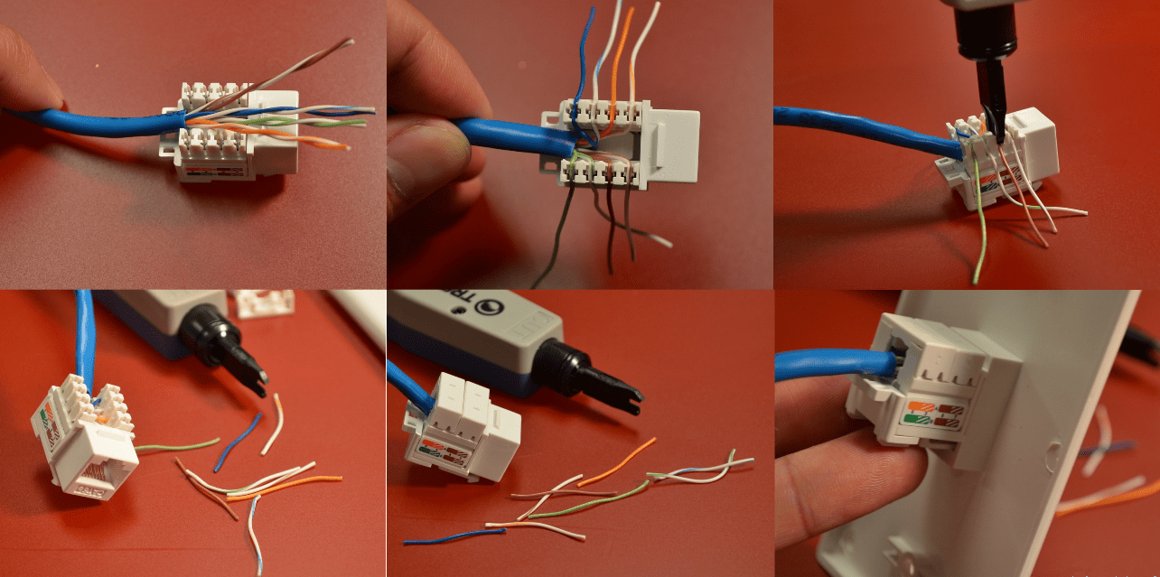
 Next we need the power outlet itself. This model of Schneider power socket uses a clamping mechanism for crimping cables. The clips in the photo below are raised. By the way, they also have a pinout diagram that will be needed in further work.
 We insert a twisted pair cable through a special hole in the clamp.
 Next, the cable needs to be fluffed up. Those. separate paired wires. After this, we install each individual wire in the corresponding color socket on the latch. At this stage, a reasonable question of choosing a pinout may arise. On the color scheme drawn on the body of the socket, there are two options - scheme A and scheme B. From
  If the first wire in the connector is “white-orange”, then we use circuit “B”.
 In general, we insert the wires into the holes corresponding to the color of the selected circuit.
 Next we snap the latch.
 You can trim off excess wires for aesthetics.
 If necessary, we crimp the second socket in a similar way.
 Next, install the socket in the socket box. In this case, it is attached with screws to the body of the external unit for external wiring. If the installation is carried out in a regular socket box, then the Schneider power socket has clamping “ears” that perfectly fix it in this case.


 Open the cover of the contact part and carefully study the markings. Each RJ45 socket can be connected in two ways:
 In most cases, the second option is used - "B". To understand where to connect which wires, carefully inspect the housing. It should indicate which standard corresponds to certain contacts.


 After installing the Internet outlet itself, all that remains is to correctly connect the cable to the router in the communication panel.


 But what should you do if you use a 4-wire telephone cable for the Internet, and the socket is a standard 8-wire socket? How to connect the circuit in this case?

 That is, immediately after placing them in their places in the slot. In this case, the core may accidentally fall out, and it will not be possible to insert it back after being cut. You will have to clean everything out again and go through the entire connection cycle again.


New
- Laser therapy (laser therapy) Laser therapeutic device "Matrix" What does the laser therapy device Matrix treat?
- Fraudulent subscriptions and fraud in Telegram Subscribers for telegram channel
- Specialty "Infocommunication technologies and communication systems" (bachelor's degree) Infocommunication technologies and communication systems 11
- Odnoklassniki: how to open my page
- How to submit water meter readings in Kazan State services portal RT meter readings
- Outputting part of an image html sprite
- Setting up additional details and additional information for 1c nomenclature additional details and information differences
- What to do when there is no registration data
- Request for data selection (formulas) in MS EXCEL Excel selection by condition macro
- Temporary temporary one-time email Temp Email, mail sites, social media registration


